- The cycle: the RTC Application Provider creates a Provisioning Session in the RTC AF at RTC-1; the RTC Media Session Handler retrieves the resulting configuration at RTC-5, then uses dynamic policies, Network Assistance and reporting during the session.
- APIs: subsets of the TS 26.510 provisioning and media session handling APIs, plus one RTC-specific provisioning API for STUN, TURN and signalling services.
- Signalling and media: SWAP over WebSocket for operator-hosted sessions; media over SRTP and data over the WebRTC data channel.
- Release 19: dynamic policies gain PDU handling and marking enhancements; endpoints gain media capability requirements and timed metadata over the data channel.
The features
The RTC features and the APIs that provision and use them (TS 26.113 table 4.1-1).
| Feature | What it does | At RTC-1 | At RTC-5 |
|---|---|---|---|
| Content configuration | Configures content delivery for a Provisioning Session | Provisioning Sessions; Real-time Media Communication provisioning | Service Access Information |
| Metrics reporting | The RTC endpoint uploads metrics reports according to a provisioned Metrics Reporting Configuration | Provisioning Sessions; Metrics Reporting Provisioning | Service Access Information; Metrics Reporting |
| Consumption reporting | The RTC endpoint reports on currently consumed content according to a provisioned Consumption Reporting Configuration | Provisioning Sessions; Consumption Reporting Provisioning | Service Access Information; Consumption Reporting |
| Dynamic Policy invocation | The RTC endpoint activates traffic treatment policies selected from the Policy Templates of its Provisioning Session | Provisioning Sessions; Policy Templates Provisioning | Service Access Information; Dynamic Policy |
| Network Assistance | The RTC endpoint requests bit rate recommendations and delivery boosts from the RTC AF | Service Access Information; Network Assistance | |
| Edge content processing | Edge resources are provisioned for processing content in RTC sessions | Provisioning Sessions; Edge Resources Provisioning |
Provisioning
To configure ICE candidates, dynamic policies or reporting, the RTC Application Provider creates a Provisioning Session in the RTC AF. The provisioning API at RTC-1 is a subset of the TS 26.510 provisioning APIs. The provisioning procedure is common to the different collaboration scenarios.
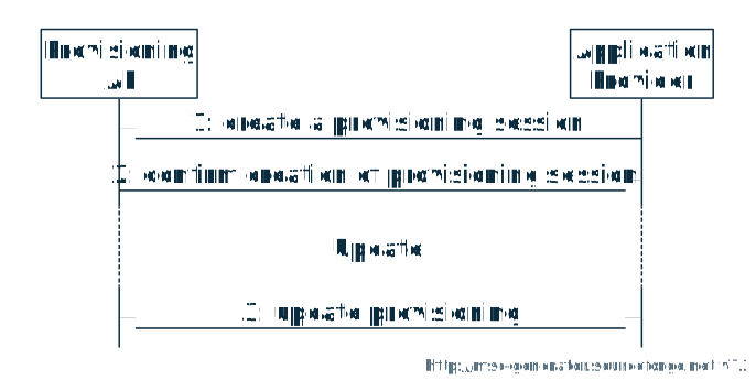
APIs at RTC-1 (TS 26.113 V19.2.0, table 6.1-1)
| API | TS 26.510 clause | Resource under 3gpp-maf-provisioning/v1 |
|---|---|---|
| Provisioning Sessions | 8.2 | provisioning-sessions |
| Server Certificates Provisioning | 8.4 | provisioning-sessions/{provisioningSessionId}/certificates |
| Edge Resources Provisioning | 8.6 | provisioning-sessions/{provisioningSessionId}/edge-resources-configurations |
| Policy Templates Provisioning | 8.7 | provisioning-sessions/{provisioningSessionId}/policy-templates |
| Real-time Media Communication Provisioning | 8.10 | provisioning-sessions/{provisioningSessionId}/rtc-configuration |
| Metrics Reporting Provisioning | 8.11 | provisioning-sessions/{provisioningSessionId}/metrics-reporting-configurations |
| Consumption Reporting Provisioning | 8.12 | provisioning-sessions/{provisioningSessionId}/consumption-reporting-configuration |
Content hosting, content publishing, content preparation templates and event data processing are not part of the RTC subset.
ICE and signalling configuration
The Real-time Media Communication provisioning API enables or advertises STUN, TURN and SWAP services, to facilitate communication between RTC endpoints. These services may be provided by the Media AS itself or provisioned by the Media AF. There is at most one RTC Configuration resource per Provisioning Session, created, retrieved, updated and destroyed with POST, GET, PUT, PATCH and DELETE.
| Property | Meaning |
|---|---|
enableStunService, stunEndpoints | If true, the Media AS provides a STUN service to the Media Session Handler for RTC sessions of the Provisioning Session; if false, the Application Provider may list its own trusted STUN endpoints |
enableTurnService, turnEndpoints | The same, for a TURN service |
enableSwapService, swapEndpoints | The same, for a SWAP signalling service |
edgeResourcesConfigurationId | When present, the Media AS for this configuration is realised as one or more EAS instances, per the referenced Edge Resources Configuration |
Each endpoint gives a domain name, port numbers, and optionally credentials and a server certificate.
The configuration procedure pre-configures the RTC Media Session Handler with information it makes available to RTC applications at RTC-6: the location and capabilities of trusted ICE functions and of trusted WebRTC Signalling Functions, and the edge configuration. After the Application Service Provider has provisioned its resources, the Media Session Handler requests the configuration from the RTC AF, optionally for a given application identifier, in a single retrieval.
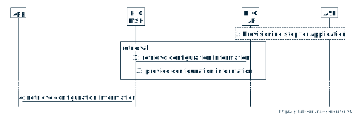
The RTC AF relays this configuration to the RTC Media Session Handler at RTC-5, in the rtcClientConfiguration of the Service Access Information, which carries trusted STUN, TURN and SWAP endpoints for use as ICE candidates. For RTC, the Service Access Information carries no streamingAccess object. If TURN credentials were not provisioned at RTC-1, the AF populates a set unique to the requesting client.
SWAP signalling
The Simple WebRTC Application Protocol (SWAP), in TS 26.113, supports collaboration scenario 3. It is an acknowledged signalling protocol for WebRTC, designed to adhere to the JSEP state machine of RFC 8829. If the RTC AS provides a WebRTC Signalling Function, an RTC Application configures itself to use one of its servers.
Click a figure to enlarge it.
- Transport: a full-duplex reliable WebSocket connection, between two endpoints or between an endpoint and a SWAP server. Point to point, one endpoint acts as the WebSocket server and listens for the incoming connection request. Through a SWAP server, enough information is provided for the server to relay messages to the other endpoint. The URI uses the
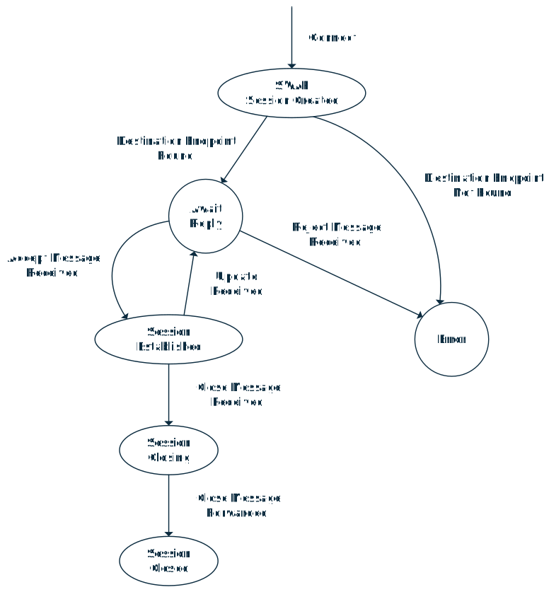
wssscheme and the path/3gpp-swap/v1/, with the subprotocol identifier3gpp.SWAP.v1in the HTTP upgrade request. - Messages: Register, Response, Connect, Accept, Reject, Update, Close and Application. An endpoint registers with the SWAP server and provides the matching criteria used to match it with incoming connection requests. Connect establishes a connection; Update may tear down media partially, such as one direction; Close terminates the entire RTC session.
- Errors: formatted as Problem Details (RFC 7807).
- Not in version 1: ICE trickling and preliminary answers.
- Security: integrity and confidentiality options are described, with consultation with SA3 recommended.
The SWAP server maintains state information about ongoing RTC sessions, as in the state machine below.
The signalling protocol for collaboration scenario 4 is for future study.
Media transport
An RTC endpoint supports the transport protocols used in WebRTC (RFC 8834), including those for interaction with firewalls, relays and NAT. Signalling information is exchanged over the WebSocket connection described above.
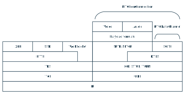
- Media: video, audio and speech over RTP for WebRTC. An endpoint that transports them supports the RTP/SAVPF profile, and encapsulates the encoded media in SRTP.
- Data: application data and metadata over the WebRTC data channel (RFC 8831), with SCTP over DTLS.
- Packet loss: endpoints offering video support the packet-loss handling of RFC 8834 and RFC 8835, with additions. Endpoints supporting video support the TMMBR and TMMBN codec control messages.
Dynamic policies
An RTC Client or an RTC AS may instantiate a Dynamic Policy in the RTC AF to configure QoS allocation in the 5G Core for a new or existing RTC session. A Dynamic Policy invoker does not modify or destroy a Dynamic Policy created by another invoker. The Dynamic Policy API is invoked as a result of SDP negotiation during the WebRTC signalling phase. The policy is chosen from the Policy Templates provisioned at RTC-1.
Dynamic policies also carry application-specific PDU handling:
- PDU Sets: an RTC AS may enable differentiated QoS treatment of groups of related downlink PDUs, by marking them with PDU Set metadata processed by the 5G System. The policy gives PDU Set QoS parameters and the media transport protocol (SRTP) of the application flow. A sending RTC endpoint then includes PDU Set identification information in the media it transmits at RTC-4m or RTC-12.
- N6-unmarked PDUs (Release 19): a PDU Set Importance value, from 1 to 15, for all N6-unmarked PDUs on the flows of the session.
- Data bursts (Release 19): data burst size and time to next burst, which assist the RAN in radio resource management.
- Expedited transfer (Release 19): the RTC Media Session Handler declares two non-GBR QoS specifications, one for expedited and one for non-expedited data transfers.
- Multiplexed media (Release 19): differentiated handling of multiplexed media flows is optional in the RTC System.
There is no support in the 5G System for differentiated QoS handling of uplink data bursts. The use of reflective QoS at RTC-12 is for future study.
Network Assistance
If AF-based Network Assistance is supported in the RTC System, the RTC Media Session Handler first creates a Network Assistance Session in the RTC AF at RTC-5, then uses it to obtain bit rate recommendations and issue delivery boost requests during the RTC session. Network Assistance is not provisioned by the Application Provider at RTC-1. As an alternative, the Media Session Handler may query the UE modem for the recommended uplink or downlink bit rate (ANBR).
QoE metrics
An RTC Client UE reports QoE metrics for the real-time media it has received, valid for speech, video and text media. The metrics scheme is urn:3GPP:ns:RTC:QM1, and an XML QoE report has the MIME type application/3gprtc-qoe-report+xml. Reporting is provisioned at RTC-1 and reports are sent at RTC-5, or at RTC-3 by an RTC AS.
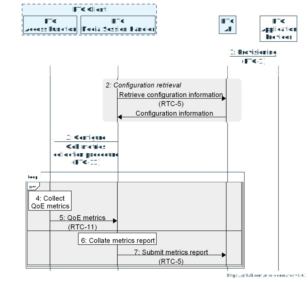
In the RTC Client, the RTC Media Session Handler obtains the metrics configuration from the RTC AF and configures metrics collection in the RTC Access Function. The Access Function collects QoE metrics about the real-time media it has received; the Media Session Handler receives them at RTC-11, collates them into metrics reports, and periodically submits the reports to the RTC AF. An RTC AS follows the same steps with its Media Function, reporting at RTC-3.
| Metric (TS 26.113 clause 15.2) |
|---|
| Corruption duration |
| Successive loss of RTP packets |
| Frame rate |
| Jitter duration |
| Sync loss duration |
| Round-trip time |
| Average codec bit rate |
The list of metrics in TS 26.506 table 4.5-1 differs: it has an average presentation latency metric and no jitter metric.
Consumption reporting
An RTC Client collects and reports at RTC-5 information about the real-time media it consumes at RTC-4 and RTC-12; an RTC AS reports at RTC-3 the media it consumes at RTC-4. One consumption report unit is included for each media component actively being received, as identified by the m= line of the negotiated SDP, and identifies the media by its media identifier (mid) or SSRC.
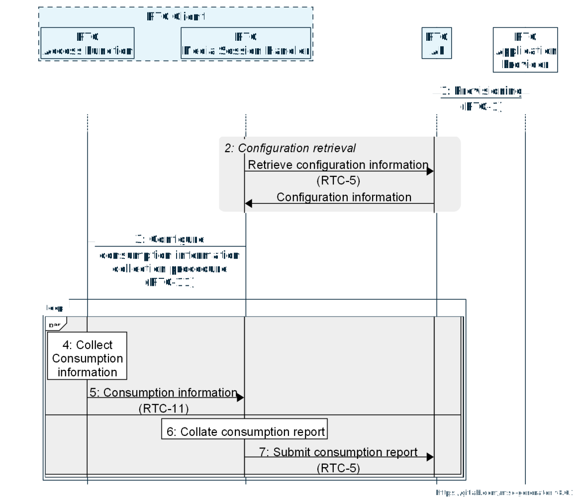
The procedure follows the same steps as metrics reporting: the RTC Media Session Handler configures collection in the RTC Access Function, receives the consumption information it collects, collates it into consumption reports and periodically submits them to the RTC AF.
Media capabilities and metadata
The APIs and protocols of TS 26.113 are not restricted to specific codecs. A terminal should implement the UE codec requirements of TS 26.114 for speech and for video, where supported. From Release 19, an RTC endpoint supporting immersive real-time communication supports the media profiles of TS 26.119 for its device type, and timed metadata of TS 26.119 may be carried over the WebRTC data channel for an XR session; the use of these metadata exchanges is for future study. Support of non-3GPP codecs is outside the scope of TS 26.113.
Edge processing
The Edge Resources Provisioning API is used by the RTC Application Provider to provision edge resource usage for the RTC sessions of a Provisioning Session. The edge-enabled architecture is on the Architecture page.
Shared with 5G Media Streaming
TS 26.510 specifies the provisioning and media session handling APIs once, for both systems, and marks each feature's applicability.
| Feature (TS 26.510 table 5.1-1) | Applicability |
|---|---|
| Real-Time media Communication (RTC) | RTC |
| Dynamic Policy instantiation | 5GMS, RTC |
| Network Assistance | 5GMS, RTC |
| QoE Metrics reporting | 5GMS, RTC |
| Consumption reporting | 5GMS, RTC |
| Content hosting, content publishing, UE data collection, reporting and exposure | 5GMS |
Release differences
- TS 26.113, Release 18 (V18.4.0): the Dynamic Policy invoker is the Media Session Handler. PDU Set marking is defined; the intention to include the optional Number of PDUs in the PDU Set field is not yet signalled in advance to the 5G Core.
- TS 26.113, Release 19 (V19.2.0): the invoker is the RTC Media Session Handler or the RTC AS. Dynamic policies add the number of PDUs in a PDU Set, N6-unmarked PDUs, data burst and expedited transfer marking, and multiplexed media. Media capabilities and metadata are added. The OpenAPI files move from version 1.0.0 to 1.1.0.
- TS 26.506, Release 19: adds data burst size, time to next burst, expedited data transfer and media transport multiplexing, and the PDU Set Importance of N6-unmarked PDUs.
- Both releases: SWAP schema corrections and the handling of the close operation (TS 26.113 V18.4.0 and V19.2.0).
Sources for this page
- The features: TS 26.113 V19.2.0, clause 4.1, table 4.1-1.
- Figures: redrawn from TS 26.506 V19.2.0, figures 5.2.1-1, 5.2.2-1, 5.2.3.1-1 and 5.2.4.1-1, and TS 26.113 V19.2.0, figures 13.1-1, 13.2.4.2-1, 13.2.4.2-2 and 13.2.4.3-1.
- Provisioning: TS 26.506 V19.2.0, clause 5.2.1; TS 26.113 V19.2.0, clauses 4.2.1 and 6.1, table 6.1-1; resource paths from TS26113_Maf_Provisioning.yaml (V19.2.0).
- ICE and signalling configuration: TS 26.506 V19.2.0, clause 5.2.2; TS 26.510 V19.2.0, clauses 5.2.10.2, 8.10.1, tables 8.10.2-1, 8.10.3.1-1 and 9.2.3.1-1; TS 26.113 V19.2.0, clauses 4.2.1, 6.3 and 10.2.
- SWAP signalling: TS 26.113 V19.2.0, clauses 4.3.2, 13.2.1 and its NOTE, 13.2.3, 13.2.4.1 to 13.2.4.5, 13.2.4.7.
- Media transport: TS 26.113 V19.2.0, clauses 9.2, 9.3, 13.1, 14.2.2.1 and 14.2.2.3.
- Dynamic policies: TS 26.506 V19.2.0, clauses 4.7.1 and NOTE 2, 4.7.2.1, 4.7.2.2, 4.7.3.1.1 NOTE 1, 4.7.3.2 and 7.2.2; TS 26.113 V19.2.0, clauses 10.3.1 to 10.3.4.
- Network Assistance: TS 26.113 V19.2.0, clause 10.4; TS 26.510 V19.2.0, clause 5.2.1, NOTE; TS 26.506 V19.2.0, clause 5.3.
- QoE metrics: TS 26.506 V19.2.0, clause 4.5, table 4.5-1, clauses 5.2.3.1 and 5.2.3.2; TS 26.113 V19.2.0, clauses 6.7, 15.1, 15.2.2 to 15.2.8 and 15.3.1.
- Consumption reporting: TS 26.506 V19.2.0, clauses 4.6 and 5.2.4.1; TS 26.113 V19.2.0, clauses 10.6.2 and 10.6.3.
- Media capabilities and metadata: TS 26.113 V19.2.0, clauses 9.2 and its NOTE, and 16 and its NOTE.
- Edge processing: TS 26.113 V19.2.0, clause 6.5.
- Shared with 5G Media Streaming: TS 26.510 V19.2.0, clause 5.1, table 5.1-1.
- Release differences: TS 26.113 V18.4.0 and V19.2.0, clause 10.3, annex D and OpenAPI files; TS 26.506 V18.6.0 and V19.2.0, clause 4.7 and annex C.