This documentation is currently under development and subject to change. If you are interested in becoming a member of the 5G-MAG and actively participating in shaping this work, please contact the Project Office
MBS Service Layer Aspects
This page summarises the MBS user-service layer: the higher-level abstraction (defined in TS 26.502) that sits on top of the low-level MBS Services, the control-plane and user-plane functions that realise it (the MBSF and the MBSTF), and the reference points that connect them. It complements the Service and System Aspects page, which covers the underlying 5G Core architecture, and the RAN Aspects page, which covers the radio side. For acronyms used here, see the Glossary.
Two points apply to every figure and interaction described below (stated once here rather than repeated per figure):
The architecture figures on this page are subject to change following ongoing discussion about the security architecture. In particular, there is a proposal for the MBSF to be directly attached to the user plane in order to support the user plane client authentication procedure defined in TS 33.501 annex W.4.
Where the MBS Application Provider (the AF/AS) is deployed outside the Trusted Data Network (DN), it reaches the control-plane functions via the Network Exposure Function (NEF) rather than directly (via reference point N33). This applies to every AF/AS interaction described below.
Reference points at a glance
The service-layer reference points used below are:
- Nmb10: AF/AS provisions MBS User Services on the MBSF (via the NEF as N33+Nmb5 when outside the trusted domain).
- Nmb1: MBSF provisions low-level MBS Services on the MB-SMF.
- Nmb2: MBSF configures MBS Distribution Sessions on the MBSTF.
- Nmb8: AF/AS ingests content into the MBSTF.
- Nmb9: MBSTF forwards the resulting MBS data to the MB-UPF.
- Nmb13 (or N33+N29mb via the NEF): AF/AS provisions low-level MBS Services directly on the MB-SMF, bypassing the user-service layer.
- N6mb: AF/AS injects MBS data directly into the MB-UPF (used only when the user-service layer is bypassed).
- MBS-4-MC: multicast/broadcast user-plane delivery of MBS data (and announcements) to the MBSTF Client.
- MBS-4-UC: unicast object-repair interaction between the MBSTF Client and the MBS AS.
- MBS-5: unicast retrieval of the MBS User Service Announcement by the MBSF Client.
- MBS-7: client API exposing received data to the MBS-Aware Application.
Load-bearing acronyms used below: AF (Application Function); AS (Application Server); MB-SMF (Multicast/Broadcast Session Management Function); MB-UPF (Multicast/Broadcast User Plane Function); NEF (Network Exposure Function); TMGI (Temporary Mobile Group Identity); FLUTE (File Delivery over Unidirectional Transport).
Media Streaming sessions over MBS User Services (TS 26.501)
This clause of TS 26.501 is currently a placeholder (marked "Void" in the specification) and has no content yet; it is reserved for future definition of how 5G Media Streaming sessions run over MBS User Services.
MBS User Services (TS 26.502)
The primary goal of the MBS User Services architecture specified in TS 26.502 is to provide a higher-level abstraction on top of MBS Services that is more useful to a Content Service Provider, referred to in TS 26.502 as an MBS Application Provider. This entity plays the role of the AF/AS in the lower-level MBS Services architecture defined in TS 23.247 and described below.
The MBS User Services abstraction comprises three principal data entities:
- The MBS User Service includes basic top-level metadata about itself, such as a type (broadcast or multicast) name, description and main service language.
- Each MBS User Service defines a set of MBS User Data Ingest Sessions. These optionally define a time schedule for activation (if they are not intended to run 24/7) as well as a set of MBS Distribution Sessions, one for each service component or regional variant of the parent MBS User Service.
- Each MBS Distribution Session corresponds to one MBS Session in the MB-SMF. In the case of regional variations, the MBS Distribution Session is provisioned with a target region and, as a result, each one maps to a location-specific MBS Service.
For example, a sports channel could be one MBS User Service; its weekend live coverage could be an MBS User Data Ingest Session scheduled Saturday to Sunday; and within that, separate MBS Distribution Sessions could carry the video component and a regional commentary variant.
The overall system architecture for MBS User Services (green) and MBS Services (purple) is depicted in figure 3.2-1. The (green) MBS User Services functions are optional in an MBS System: it is valid to omit them entirely, in which case the AF/AS must provision low-level MBS Services directly with the (purple) MB-SMF at reference point Nmb13 (or N33+N29mb, if outside the trusted network), and then inject MBS data directly into the (purple) MB-UPF at reference point N6mb. The MBSF and MBSTF functions that realise the user-service layer are described in the subsections that follow.
The figure below shows the overall system architecture. Colour is used only to group functions: the MBS User Services functions are shown in green and the lower-level MBS Services functions in purple; the same grouping is stated in the caption so it does not depend on the colours.
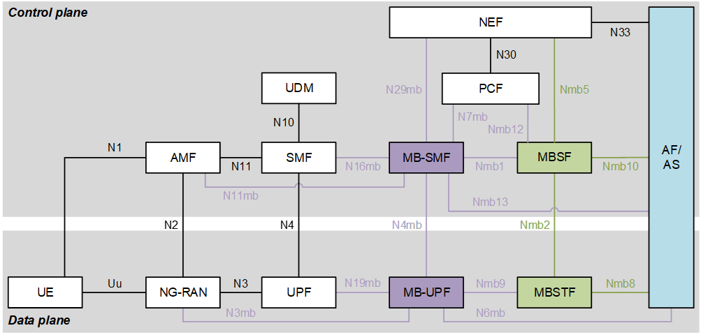
As with existing Network Functions in the 5G Core, the additional control plane entities (top half of the figure) communicate using service-based interfaces based on HTTP/2-based RESTful interactions defined using OpenAPI schemas. In the data plane (bottom half of the figure), individual protocols are defined at each reference point.
Two MBS User Services functions are defined by SA2 in TS 23.247, but their detailed design was delegated to SA4:
-
The Multicast–Broadcast Service Function (MBSF) is the control plane entity responsible for maintaining the provisioning state for MBS User Services and for controlling their life-cycle. The AF/AS provisions each MBS User Service at reference point Nmb10 by invoking the Nmbsf service. (If the AF/AS resides outside the trusted domain, the Nmbsf service is instead invoked via the NEF at reference point N33+Nmb5.) A set of MBS User Data Ingest Sessions is provisioned underneath the umbrella of the MBS User Service, each one comprising one or more MBS Distribution Sessions. Based on the set of MBS Distribution Sessions provisioned, the MBSF invokes the Nmbsmf service on the MB-SMF at reference point Nmb1 to provision corresponding low-level MBS Services, and also configures a corresponding set of MBS Distribution Sessions in the MBSTF by invoking the Nmbstf service at reference point Nmb2.
- Reference point Nmb13 (or N33+N29mb via the NEF if the AF/AS resides outside the trusted domain) may still be used in parallel with Nmb10 when MBS User Services are in play. The AF/AS may pre-allocate TMGIs for MBS Distribution Sessions by invoking the Nmbsmf_TMGI_Allocate service operation directly, and then cite the allocated TMGI in a subsequent provisioning request to the MBSF. However, the MBSF is also able to allocate TMGIs as a side-effect of MBS User Service provisioning, and this simpler procedure is preferable in the common case where the AF/AS does not need pre-allocation of a TMGI.
-
The Multicast–Broadcast Service Transport Function (MBSTF) is the user plane entity responsible for ingesting content into the MBS System from the AF/AS (when required to do so by the MBS User Data Ingest Session activation schedule) at reference point Nmb8. The content ingest protocols at this reference point are defined in TS 26.517. The MBSTF supports an object-based distribution method based on FLUTE and a packet-based distribution method that simply forwards ingested packet payloads. For both distribution methods, the resulting packet stream of MBS data is forwarded to the downstream MB-UPF via reference point Nmb9.
- Reference point N6mb is not relevant when MBS User Services are in play.
In addition, TS 26.502 defines a third function:
- The Multicast–Broadcast Service Application Server (MBS AS) supports unicast-based object repair for the object distribution method. If an MBS Client does not successfully receive an object intact, it can request the missing portion(s) from the MBS AS using an HTTP byte-range request, if the optional MBS AS is deployed.
The figure below shows how these three core functions interact with other entities in the MBS System.
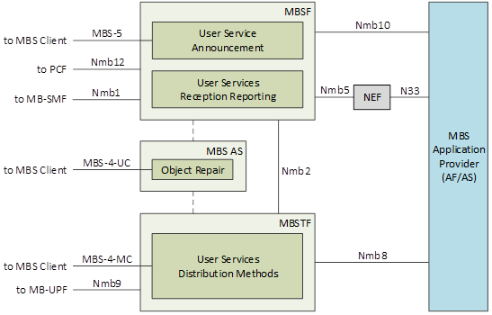
Shortly before an MBS User Data Ingest Session becomes active (e.g. according to its activation schedule), the MBSF provisions all necessary MBS Sessions in the MB-SMF (via reference point Nmb1) and corresponding MBS Distribution Sessions in the MBSTF (via reference point Nmb2). Data ingest (object or packet, as appropriate to each provisioned MBS Distribution Session) then commences at reference point Nmb8.
In addition, the MBSF compiles an MBS Distribution Session Announcement for each MBS Distribution Session provisioned in the activated MBS User Data Ingest Session and bundles them into an MBS User Service Announcement. This is then made available for unicast retrieval by MBS Clients at reference point MBS-5 and/or for carouselling over an MBS User Service Announcement Channel at reference point MBS-4-MC. The configuration of MBS User Service Announcement Channel(s) – in band with each MBS Distribution Session or out of band in a special-purpose MBS Distribution Session with its own TMGI – may vary between deployments of the MBS System. The syntax for MBS User Service Announcements is specified in TS 26.517 clause A.1.1 (XML schema language) and clause A.2.1 (OpenAPI YAML schema). These schemas allow MBS User Service Announcements for several different MBS User Services currently active in the MBS System to be bundled together for more efficient delivery at reference point MBS-5 and/or MBS-4-MC. TS 26.502 defines additional entities in the UE, as shown in the figure below:
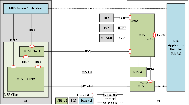
The exact TS 26.502 figure number for the UE-side entities shown above could not be confirmed from available context. The previous figure (network architecture) is figure 4.2.2-1; this UE-side figure is a separate figure. Verify the correct figure number against TS 26.502.
The MBS Client is divided into two subfunctions:
-
The MBSF Client interacts with the MBSF at the unicast user plane reference point MBS-5 (if available in the MBS System) to retrieve the MBS User Service Announcement via unicast. Otherwise (or additionally) the MBS User Service Announcement is made available to the MBSTF Client via the multicast user plane reference point MBS-4-MC, and then delivered to the MBSF Client via an internal client API.
-
The MBSTF Client receives MBS data (including MBS User Service Announcements, if any) as part of an MBS Distribution Session via the multicast/broadcast user plane reference point MBS-4-MC.
-
In the case of an MBS Distribution Session provisioned to use the packet distribution method, the received packets are exposed directly to the MBS-Aware Application via a client API at reference point MBS-7.
-
In the case of an MBS Distribution Session provisioned to use the object distribution method, the objects are reconstructed by the MBSTF to the best of its ability from the received MBS data (FLUTE packets) before exposing them to the MBS-Aware Application at reference point MBS-7, for example via a local HTTP server. Prior to object exposure, the MBSTF Client may interact with the MBS AS at reference point MBS-4-UC to perform HTTP-based object repair. (If there is insufficient time to do this, or if reference point MBS-4-UC is not instantiated in the MBS System deployment, incomplete objects are returned to the MBS-Aware Application and it may then use higher-level object repair functionality to recover lost data.)
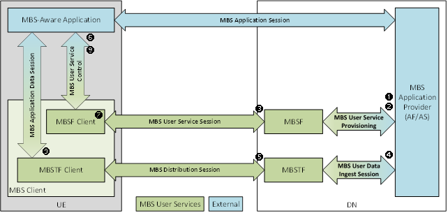
The general organisation of sessions in the MBS User Services domain is shown in the following figure:
Object distribution versus packet distribution
The MBSTF supports two distribution methods, and the choice affects both what the network does and what the client sees.
- In the packet distribution method, the MBSTF forwards ingested packet payloads with minimal processing towards the MB-UPF, and the MBSTF Client exposes the received packets directly to the MBS-Aware Application at reference point MBS-7. This suits content that is already framed for transport, for example an RTP or MPEG-2 TS stream, where the transport framing is preserved end to end.
- In the object distribution method, discrete files (objects) are carried in a FLUTE session as Asynchronous Layered Coding (ALC) packets. The MBSTF Client reassembles each object from the received packets before exposing it, typically via a local HTTP server. Because delivery is one-way and lossy, the object method is where object repair matters: if an object arrives incomplete, the client can fetch the missing byte ranges over unicast from the MBS AS at reference point MBS-4-UC, and only falls back to returning an incomplete object when repair is unavailable or there is no time for it.
For DASH or HLS media, the object method maps segments to objects and the presentation manifest becomes a Service Entry Point object. The MBSTF can operate in a streaming mode, scheduling object delivery in real time from a manifest such as a DASH MPD, or in single-shot, collection and carousel modes for file delivery. Which of these the 5G-MAG reference tools implement is listed on the MBS scope page.
Session life-cycle and announcement
The provisioning and activation flow is time-driven. An MBS User Data Ingest Session may carry an activation schedule; shortly before it becomes active, the MBSF provisions the required low-level MBS Services on the MB-SMF (Nmb1) and the corresponding MBS Distribution Sessions on the MBSTF (Nmb2), after which content ingest begins at Nmb8. When the ingest session deactivates, the MBSF tears these down again. This lets a service that is not on air 24/7 (weekend sports coverage, a scheduled event) hold radio and core resources only while it is live.
Discovery is handled by the MBS User Service Announcement. The MBSF builds one MBS Distribution Session Announcement per distribution session and bundles them, together with the session access information a client needs (TMGI, delivery method, media metadata), into an MBS User Service Announcement. Clients obtain it either by unicast pull from the MBSF (MBS-5) or by listening to an announcement carousel delivered over MBS itself (MBS-4-MC), in band with a distribution session or out of band in a dedicated announcement session with its own TMGI. Several active services can be bundled into one announcement for efficient delivery.
Service-based interfaces and protocols
The control-plane reference points (Nmb10, Nmb1, Nmb2, and the NEF-mediated variants) use 5G service-based interfaces: HTTP/2 RESTful APIs described by OpenAPI schemas, consistent with the rest of the 5G Core. The user-plane reference points each define concrete protocols instead: content ingest at Nmb8 and the MBSTF-to-MB-UPF hand-off at Nmb9 are defined in TS 26.517, which also specifies the FLUTE/ALC object carriage, the packet distribution format and the XML and OpenAPI schemas for the User Service Announcement. This split (service-based APIs on the control plane, defined protocols on the user plane) mirrors the figure above and is the same pattern used throughout the 5G Core.
These identifiers on this page were not confirmed against a primary source (the 3GPP portal blocks automated access): the reference-point names and mappings (Nmb1, Nmb2, Nmb8, Nmb9, Nmb10, Nmb13, N33+Nmb5, N33+N29mb, N6mb, MBS-4-MC, MBS-4-UC, MBS-5, MBS-7); the figure numbers cited (TS 26.502 figure 4.2.2-1 and the UE-side figure, and TS 26.501 figure 4.5.1-1); the TS 26.517 schema clauses (A.1.1, A.2.1); and the TS 33.501 annex W.4 reference. Verify against the specific TS 23.247, TS 26.502, TS 26.517 and TS 26.501 versions you are targeting.